Use of 3D Printing Technologies in Foundry Manufacturing
3D Printing as a New Stage in the Development of Foundry Engineering
Foundry manufacturing has existed since approximately 3200 BC and continues to play a vital role in modern industry, including mechanical engineering, automotive manufacturing, energy production, and heavy industry. Its primary advantage lies in the ability to produce components with complex geometries that are often impossible or economically inefficient to manufacture using alternative technologies.
For a long period, the only practical alternative to traditional metal casting was subtractive machining. However, the advancement of additive manufacturing and metal 3D printing has introduced new opportunities for optimizing part geometry, mechanical strength, and weight reduction.
Over the past three to four years, the adoption of industrial additive manufacturing systems has led to the increasing use of 3D-printed patterns, cores, and core boxes with high geometric complexity in foundry operations. This trend has driven many foundries to establish in-house digital design and additive manufacturing departments, significantly reducing lead times, lowering dependency on external suppliers, and facilitating the implementation of reverse engineering for the restoration or optimization of existing cast components.
Foundry Casting Methods and the Role of 3D Printing
Casting methods are classified according to the type of metal, geometric complexity, casting size, and required dimensional accuracy and surface quality. At present, 3D-printed patterns and cores are most commonly applied in two major casting processes.
Investment Casting (Lost-Wax Casting)
In investment casting, highly complex models are melted or burned out during the process. Traditionally, wax patterns produced using expensive tooling are required, with each casting necessitating an individual model. As a result, additive manufacturing becomes a cost-effective solution for small production series and geometrically complex components.
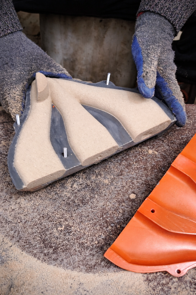
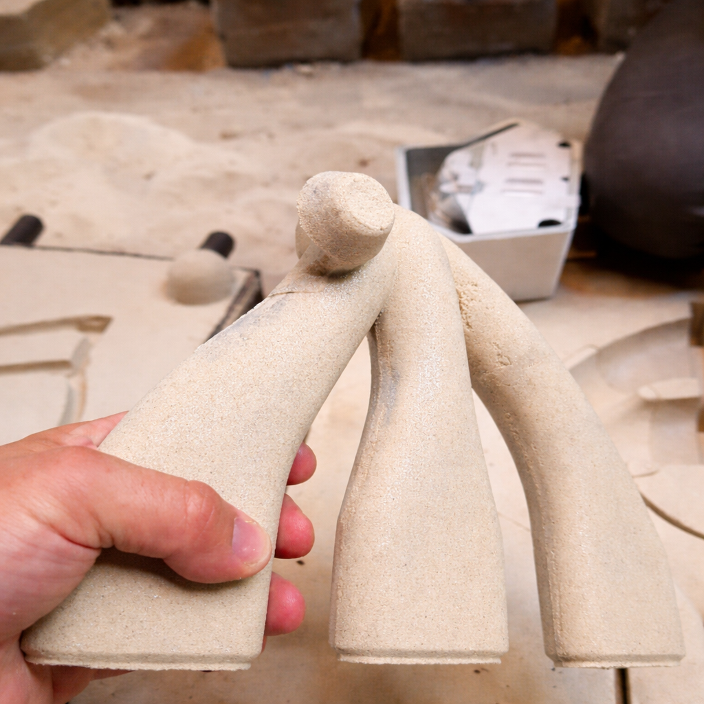
Sand Casting
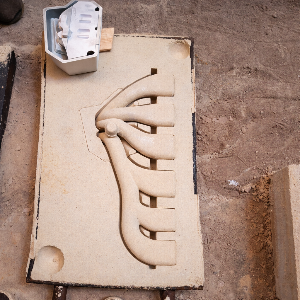
Sand casting represents the most accessible and widely adopted method for integrating additive technologies into foundry production. The mold is created by compacting molding sand mixed with additives and furan resin around a pre-positioned pattern. This produces an accurate negative of the external geometry, while core boxes define the internal cavities of the casting.
This process is particularly suitable for FDM (Fused Deposition Modeling) 3D printing, as it combines low tooling costs, high flexibility, and short implementation times.
Sand casting remains the most widely used and industry-friendly method for incorporating 3D-printed tooling, especially in the production of grey cast iron components. Applications range from braking systems for high-speed trains and industrial machine housings to automotive exhaust manifolds and components for the defense and metalworking industries.
For simpler parts, foundries often rely on conventional tooling made from wood, metal, or engineering plastics. Even in these cases, additive manufacturing can offer lower production costs when larger quantities or rapid design modifications are required.
An additional approach involves casting using sacrificial 3D-printed patterns, manufactured from specialized materials. These patterns burn out or disintegrate during metal pouring, enabling the production of extremely complex geometries and further expanding the capabilities of modern foundry engineering.
Tooling Manufacturing Methods: Traditional vs. Additive Technologies
This section compares conventional and additive methods for producing tooling used in sand casting, focusing on technological, economic, and operational factors that influence the selection of an optimal manufacturing process.
Traditional Tooling Manufacturing Methods
Manual Wood Pattern Making
Historically, tooling was handcrafted from wood by highly skilled craftsmen. Today, such expertise is increasingly rare, and the process is slow and labor-intensive, particularly for complex geometries. Wood is also prone to deformation over time, negatively affecting casting accuracy.
CNC-Machined Wooden Tooling
CNC machining reduces production time and minimizes manual finishing. However, wood remains sensitive to humidity and temperature variations, and material inconsistency can still affect dimensional stability. Additional investment in CNC equipment is also required.
CNC-Machined Aluminum Tooling
Aluminum tooling is considered the industry standard in terms of durability, wear resistance, and surface quality. It provides excellent repeatability but involves high production costs, specialized software, skilled personnel, and significant tooling expenses.
Engineering Plastics
Engineering plastics serve as an alternative to aluminum, offering reduced machining time and tool wear while providing sufficient strength and stability for many foundry applications.
Additive Manufacturing Technologies and New Opportunities
FDM 3D Printing
FDM additive manufacturing eliminates the need for traditional machining, resulting in lower costs and significantly shorter lead times. Materials such as PLA and ABS enable rapid prototyping and functional tooling production. Limitations include the need for surface post-processing, potential deformation in complex geometries, and lower durability compared to metal tooling.
Binder Jetting and Sintering Technologies
Binder jetting represents the most advanced additive method for tooling production. It offers low raw material costs, extremely short production cycles, and eliminates the need for post-processing. Cores can be produced directly without core boxes, significantly reducing component count and design time. Limitations include high equipment costs, specialized infrastructure requirements, and the need for highly trained personnel.
The choice between traditional and additive tooling manufacturing methods depends on geometric complexity, accuracy requirements, production volume, and economic feasibility. In many cases, additive manufacturing provides a highly competitive and flexible solution for modern foundry operations.
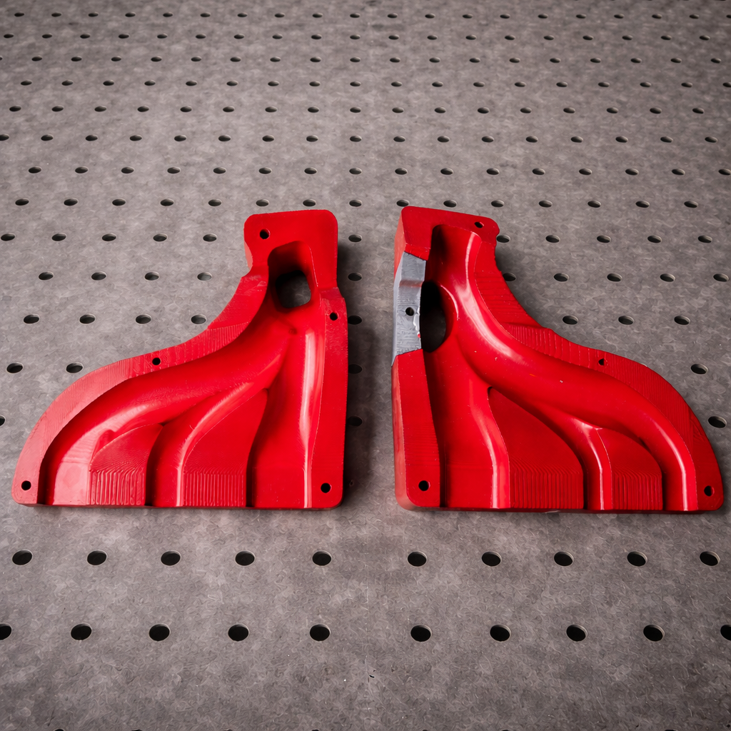
Practical Application: Manufacturing an Exhaust Manifold Using FDM Printing and Sand Casting
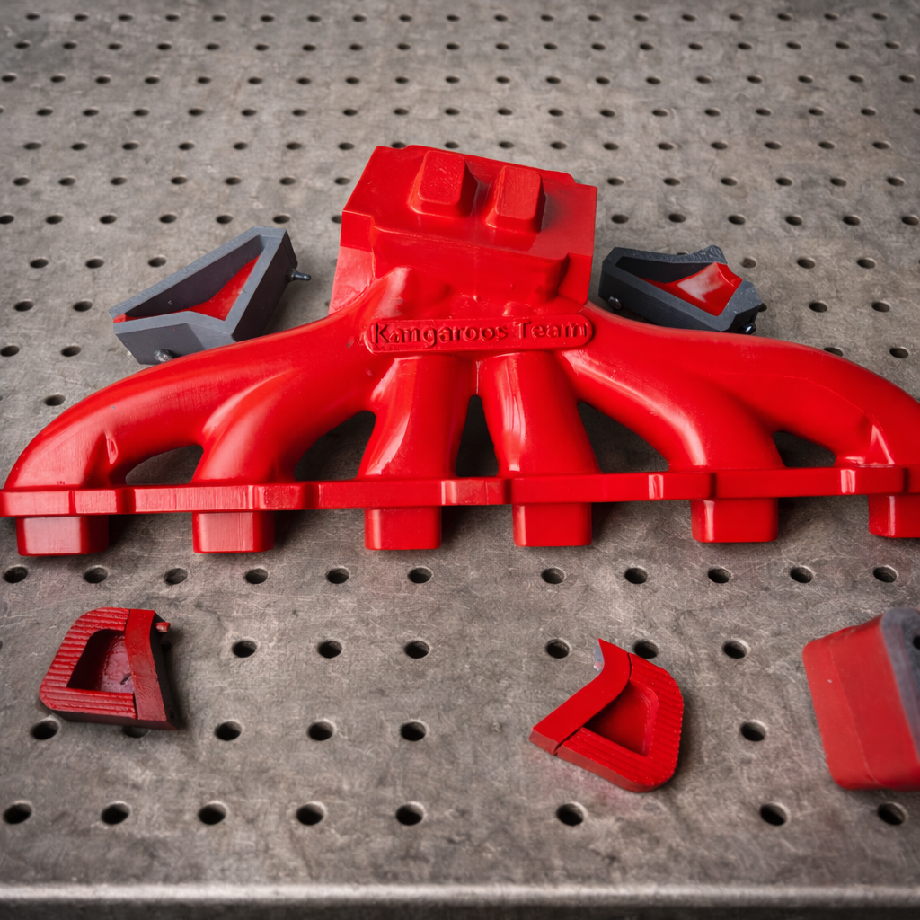
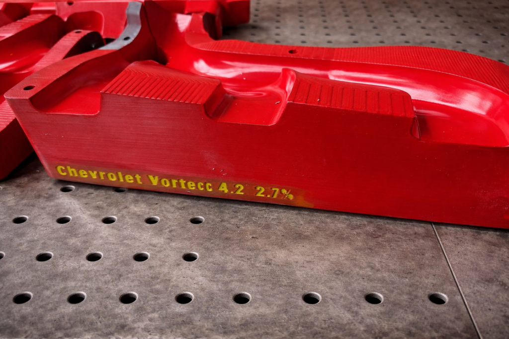
This case study examines the production of tooling for grey cast iron castings using an industrial FDM 3D printer and high-quality PLA filament. The component is an exhaust manifold with turbocharger and wastegate outlets for a six-cylinder engine, representing a typical example of complex foundry components with stringent geometric and functional requirements.
The manifold is designed for engine modification aimed at significantly increasing power output through turbocharger installation. It is intended for automotive enthusiasts, drift competitors, and brand-specific communities rather than professional motorsport due to its relatively high weight.
The primary difference from a standard exhaust manifold lies in the additional turbocharger and wastegate outlets. The wastegate prevents turbocharger overload by diverting excess exhaust gases directly into the exhaust system. When properly configured, such systems can substantially increase engine power, with each manifold individually designed to match the engine, turbocharger, and available space in the engine bay.
The design process begins by defining the spatial relationship between the cylinder head flange, turbocharger flange, and wastegate flange. While the overall design methodology remains conventional, reverse engineering is used to capture input geometry from an existing component.
The tooling described in this example is designed for manual molding. In mechanized molding systems, geometry would be constrained by machine limitations, requiring a different design approach. Nevertheless, FDM technology supports both manual and mechanized molding applications, with ABS often recommended for specific tooling elements in automated processes.
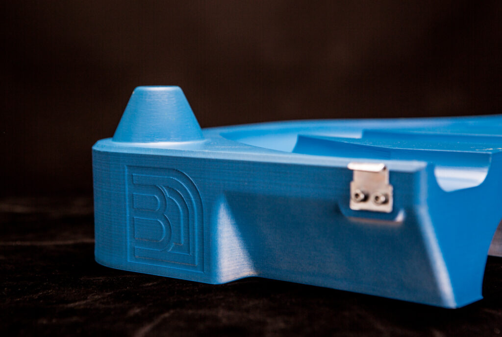
The workflow starts with rapid prototyping using a larger nozzle and lower resolution to validate shape and dimensions. This step may be repeated multiple times until the desired result is achieved. After customer approval, detailed tooling design follows, including two core boxes, external patterns, and auxiliary cores for inaccessible areas.
Core boxes are produced using a high-precision printer, while the remaining components are manufactured on an industrial FDM printer. Post-processing is mandatory and includes mechanical surface finishing and the application of a protective coating to improve wear resistance. The final result is a fully machined cast exhaust manifold successfully installed on a turbocharged engine.
This case study demonstrates how modern additive manufacturing technologies can be effectively integrated into traditional foundry production. The combination of digital design, additive tooling fabrication, and sand casting enables the production of complex castings with reduced lead times and optimized costs. In the long term, such solutions provide foundries with increased flexibility, enhanced competitiveness, and the ability to rapidly adapt to individual customer requirements.